

Slewing Bearings in Wind Turbines: Yaw & Pitch Bearing Requirements Explained

We are always ready for you.

Slewing Bearings in Wind Turbines:
Yaw & Pitch Bearing Requirements Explained
June 2026 | Anhui Yuanfeng Slewing Bearing Co., Ltd.
Wind turbines ask more of their slewing bearings than almost any other application. A crane bearing rotates continuously and can be inspected or replaced with relative ease. A bearing at the top of a wind turbine — installed 80 to 120 metres above ground — must operate reliably for 20 years with minimal intervention, under loads that shift constantly in direction and magnitude, in environments ranging from desert heat to Arctic cold to rain and dust. Understanding what separates a wind turbine slewing bearing from a standard industrial bearing is essential for engineers specifying these components and procurement teams evaluating suppliers.
At Anhui Yuanfeng, we manufacture slewing bearings for onshore wind turbine applications, covering both yaw and pitch bearing configurations. Below is the technical framework we use when working with wind energy customers.
Two Bearings, Two Jobs: Yaw vs. Pitch
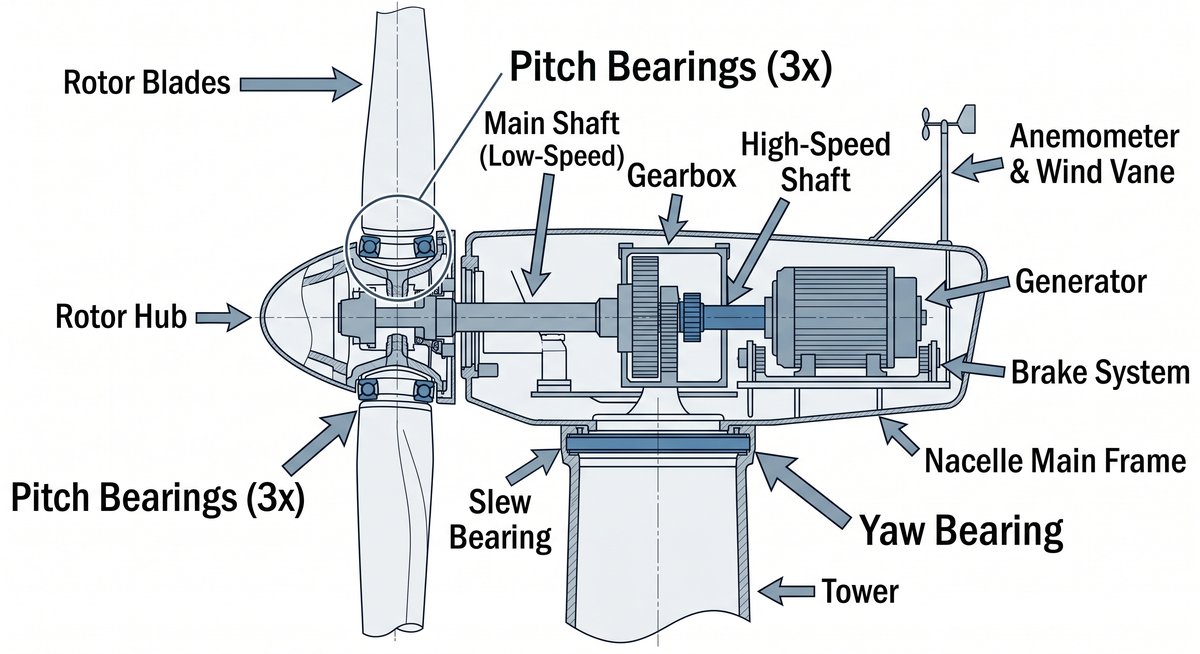
Figure 1: Cross-section of a horizontal-axis wind turbine — yaw bearing (at tower-nacelle junction) and pitch bearing (at blade root-hub connection)
A standard three-blade horizontal axis wind turbine uses four slewing bearings: one yaw bearing and three pitch bearings. Their positions in the turbine are different, and so are the demands placed on each.
The yaw bearing sits at the junction between the tower top and the nacelle — the housing that contains the gearbox, generator, and drivetrain. Its job is to rotate the entire nacelle around the vertical tower axis, continuously tracking the wind direction. Yaw rotation is slow and infrequent: the nacelle may complete only a few degrees of movement at a time, responding to wind shifts over minutes or hours. But the loads are substantial. The yaw bearing carries the full weight of the nacelle, hub, and blades, along with significant tilting moments generated by asymmetric wind loading across the rotor disc. The most common configuration is a single-row four-point contact ball slewing bearing, valued for its ability to handle combined axial, radial, and moment loads within a compact cross-section.
Pitch bearings are installed at the connection between each blade root and the hub. Each bearing allows its blade to rotate around its longitudinal axis, adjusting the blade's angle (pitch angle) in response to wind speed changes. At low wind speeds, blades pitch to capture maximum energy. As wind speed increases beyond the turbine's rated capacity, blades feather progressively to limit output and protect the structure. In emergency shutdowns, blades must reach a fully feathered position within seconds. This means pitch bearings experience a far more demanding oscillatory cycle than yaw bearings: continuous small-amplitude movements rather than occasional large rotations. Pitch bearing diameters typically range from approximately 1.5 metres on smaller onshore turbines upward, sized to match the blade root diameter. The most common type is the double-row four-point contact ball slewing bearing, which provides higher load capacity than single-row designs in a configuration suited to the confined space at the blade root.
Load Profile: What These Bearings Actually Handle
The load conditions in wind turbine slewing bearings differ fundamentally from most industrial rotating equipment.
Yaw bearings must handle tilting moments generated not just by wind pressure on the rotor disc but by gravity acting on the offset mass of the hub and blades. Axial loads (the vertical weight of the nacelle structure) and radial loads from wind thrust act simultaneously — a combined load condition that requires careful analysis rather than simple catalogue selection.
Pitch bearings operate under a different challenge: non-uniform load distribution. Because wind speed and pressure vary across the rotor disc — higher at the blade tip, lower near the hub, asymmetric under yawed conditions — pitch bearings carry loads that shift constantly around their circumference. One section of the raceway may bear the majority of the load while the rest carries little. Over a long service life, this uneven loading creates fatigue patterns that standard bearing life calculation methods, developed for uniform load distribution, do not capture accurately. The design methodology for yaw and pitch bearings is governed by NREL Design Guideline DG03 (Yaw and Pitch Bearings), updated in 2024, which provides calculation methods specifically calibrated for these oscillatory, non-uniform load conditions.
Why Standard Bearings Don't Work Here
Three factors — material, sealing, and lubrication — each require specification beyond standard industrial practice.
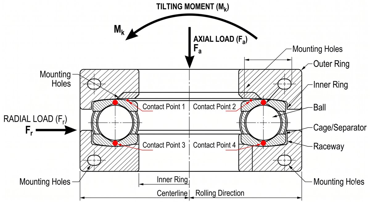
Figure 2: Four-point contact ball bearing — combined axial, radial, and tilting moment load paths
Material and Heat Treatment
The raceway steel for wind turbine slewing bearings is typically 42CrMo alloy steel. After overall quench-and-temper treatment, the ring hardness reaches 229–269 HB; raceway surface induction hardening then achieves 55–62 HRC at the contact surface while preserving a tough core. Hardened layer depth and consistency across the full raceway circumference are critical. Uneven hardening creates soft spots where contact fatigue initiates prematurely. For a pitch bearing operating under non-uniform load, a localised soft zone in the high-load sector can trigger failure well ahead of the bearing's calculated life.
Sealing Requirements
Onshore wind turbine sites face sand, dust, temperature cycling, and precipitation across all seasons. A single elastomeric lip seal is generally insufficient for long service under these conditions. Wind turbine slewing bearings typically specify multi-layer sealing: labyrinth seals combined with elastomeric lip seals, with corrosion-inhibiting grease applied to the seal interface. Seal material should be rated for the full operating temperature range and UV exposure at the installation site.
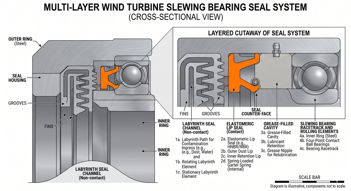
Figure 3: Multi-layer sealing configuration — labyrinth seal combined with elastomeric lip seal with corrosion-inhibiting grease interface
Lubrication
The slow oscillatory motion of pitch and yaw bearings means conventional full-rotation lubrication theory does not apply. In continuous rotation, rolling elements re-enter a fresh grease reservoir with each revolution. In oscillatory bearings, the same small arc of the raceway is contacted repeatedly, and the lubricant film in that zone is not refreshed naturally. This creates metal-to-metal contact conditions — a regime called mixed or boundary friction (κ < 1) — that accelerate wear and fretting damage.
Standard EP-2 mineral grease is generally not adequate for these conditions. Wind turbine pitch and yaw bearings require greases with enhanced extreme-pressure performance specifically validated for oscillating contact, good water resistance, and operability across the expected temperature range at the installation site.
Common Failure Modes in Wind Turbine Slewing Bearings
Understanding how these bearings typically fail is as important as knowing how to specify them.
False brinelling occurs when vibration-induced micro-movements between rolling elements and raceways cause oxidative wear at contact points, producing elliptical indentations that resemble static overload damage (Brinell marks) but result from fretting. It is particularly prevalent in pitch bearings during standstill periods — when blades are held at a fixed angle but wind-induced vibration continues to micro-load the contact zone. The characteristic sign is reddish-brown wear debris at contact points. Prevention requires grease with anti-fretting additives and, where possible, periodic small-amplitude bearing movements during extended standstill.
White etching cracks (WEC) are a more severe and less predictable failure mode, documented across the wind industry as a significant source of premature bearing replacement. WEC develop as subsurface microstructural changes in the steel, visible after etching under metallurgical microscopy as bright white areas. These cracks can propagate unpredictably and cause bearing failure well before the end of the designed service life. Contributing factors under ongoing research include hydrogen diffusion into the steel, electrical currents, and lubricant chemistry. Material traceability and steel cleanliness documentation are important procurement requirements for this reason.
Seal failure and contamination ingress is the most operationally manageable failure mode but remains a significant cause of premature bearing degradation. Seal deterioration allows moisture and contaminants into the raceway, accelerating corrosion pitting and abrasive wear. Early indicators include increased lubricant contamination in grease samples and visible discolouration at seal interfaces during routine inspection.
Specification Checklist: Questions to Ask Your Supplier
When sourcing yaw or pitch slewing bearings for onshore wind turbine applications, the following points are worth verifying with any supplier:
Material and heat treatment
- Ring steel grade (42CrMo or equivalent alloy steel)
- Base hardness after quench-and-temper (229–269 HB)
- Raceway surface hardness after induction hardening (55–62 HRC minimum)
- Hardened layer depth specification and measurement method
- Material traceability documentation (melt certificate, heat treatment records)
Geometry and clearance
- Radial and axial clearance specification — yaw bearings typically 0–50 µm; pitch bearings typically specified at negative (preloaded) clearance
- Gear module and accuracy class per applicable standard (no lower than GB/T10095.1 class 8 or equivalent DIN/ISO)
- Gear tooth profile modification coefficient
Sealing
- Seal material rated for site operating temperature range and UV exposure
- Seal configuration (single lip vs. multi-layer) and replacement accessibility
Lubrication
- Pre-filled grease type and confirmation of suitability for oscillating contact (κ < 1)
- Grease inlet specification and count
- Re-lubrication interval recommendation for the specific application
Documentation
- Dimensional inspection report
- Gear accuracy inspection report
- Heat treatment batch records
- Factory test report where applicable
Conclusion
Wind turbine slewing bearings sit in a different performance category from general industrial bearings. The combination of oscillatory loading, long unattended service life, and outdoor environmental exposure makes material quality, sealing design, and lubrication specification the primary determinants of bearing life — not just load rating alone.
For procurement teams and project engineers evaluating suppliers, the right questions go well beyond diameter and static load capacity. A supplier that provides documented evidence on heat treatment, material traceability, and grease selection — not just product claims — is one worth qualifying seriously.
Specifying slewing bearings for a wind turbine project?
Share the following with our engineering team and we will return a selection proposal within 24 hours:
- Turbine capacity (kW/MW) and rotor diameter
- Bearing position required (yaw / pitch / both)
- Installation envelope constraints (OD × ID × height)
- Site environment (onshore region, temperature range)
- Gear module and tooth count if replacing an existing bearing